
Projects
Chemical Process and Reactors
Matrix routinely designs projects for chemical plants, paper mills and other industrial facilities across the US. Our experience shines in process piping, instrumentation, reactor design, as well as tank storage, mixing and liquid loadout system.

(14) ALTERNATING SEQUENCED CONVEY INLETS THRU A 10" LINE AT 15.0 MTPH

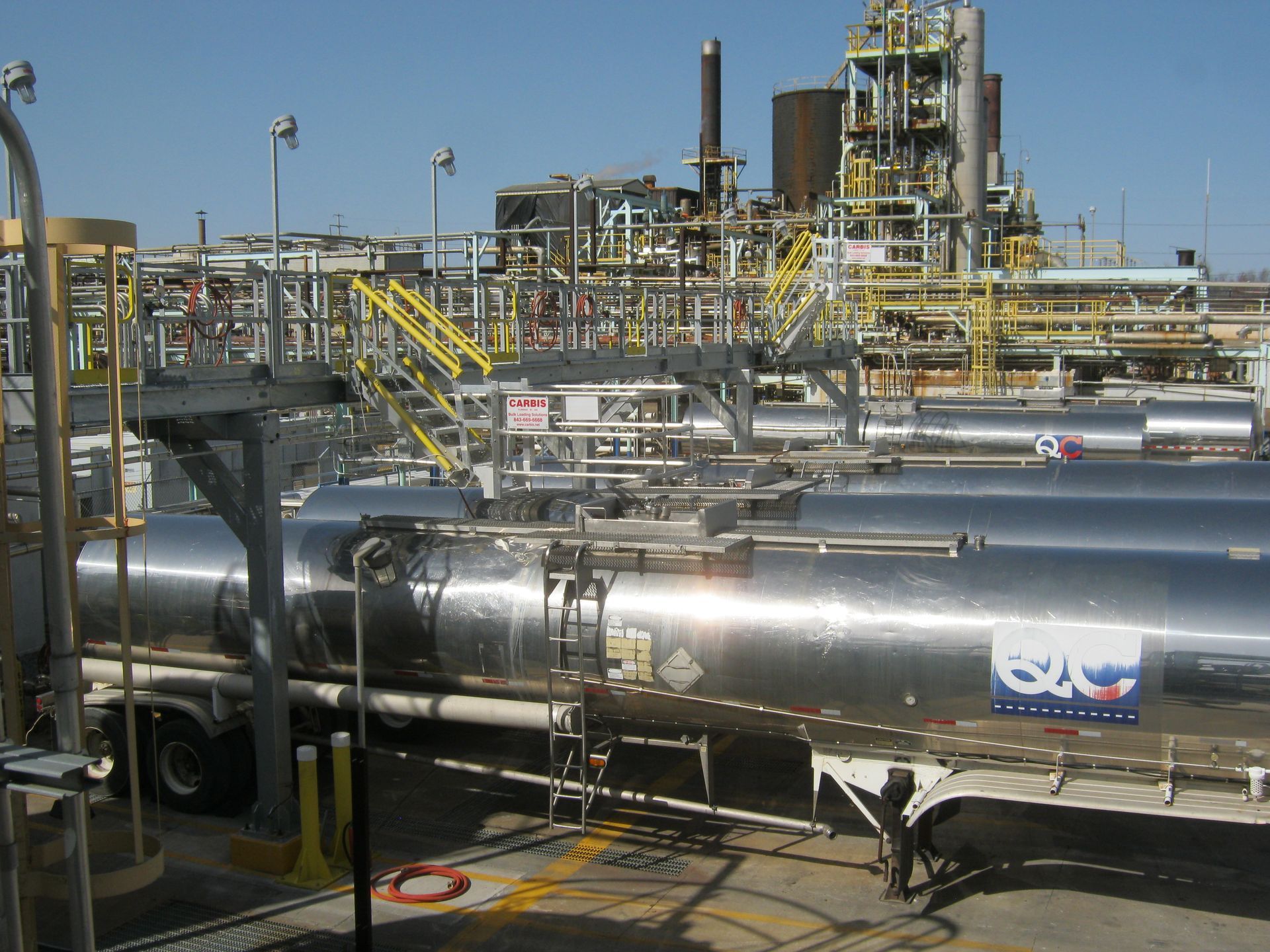
Matrix Engineering provided the structural, mechanical and electrical engineering for a drum packaging improvement project at ISP. The previous drum filling operation was manual and labor intensive requiring tipping and manhandling of 600 lb drums. The product in this case was an additive for hair spray which is responsible for its stickiness. The product is very viscous with the consistency of a very thick syrup that dries like glue. Matrix conceptualized and designed twin drum filling lines in which empty drums are palletized and filled on a scale. Loading arms for filling drums were designed to swing to either pallet scale for versatility in loading drums in either drumming line from two different tanks. Our engineers designed the piping systems associated with the product as well as caustic piping required to backwash the system and clean it out after packaging runs. We also designed an quick-acting air operated swing door system for accessing each scale with a fork lift. This area was also a Class I Div 2 area.

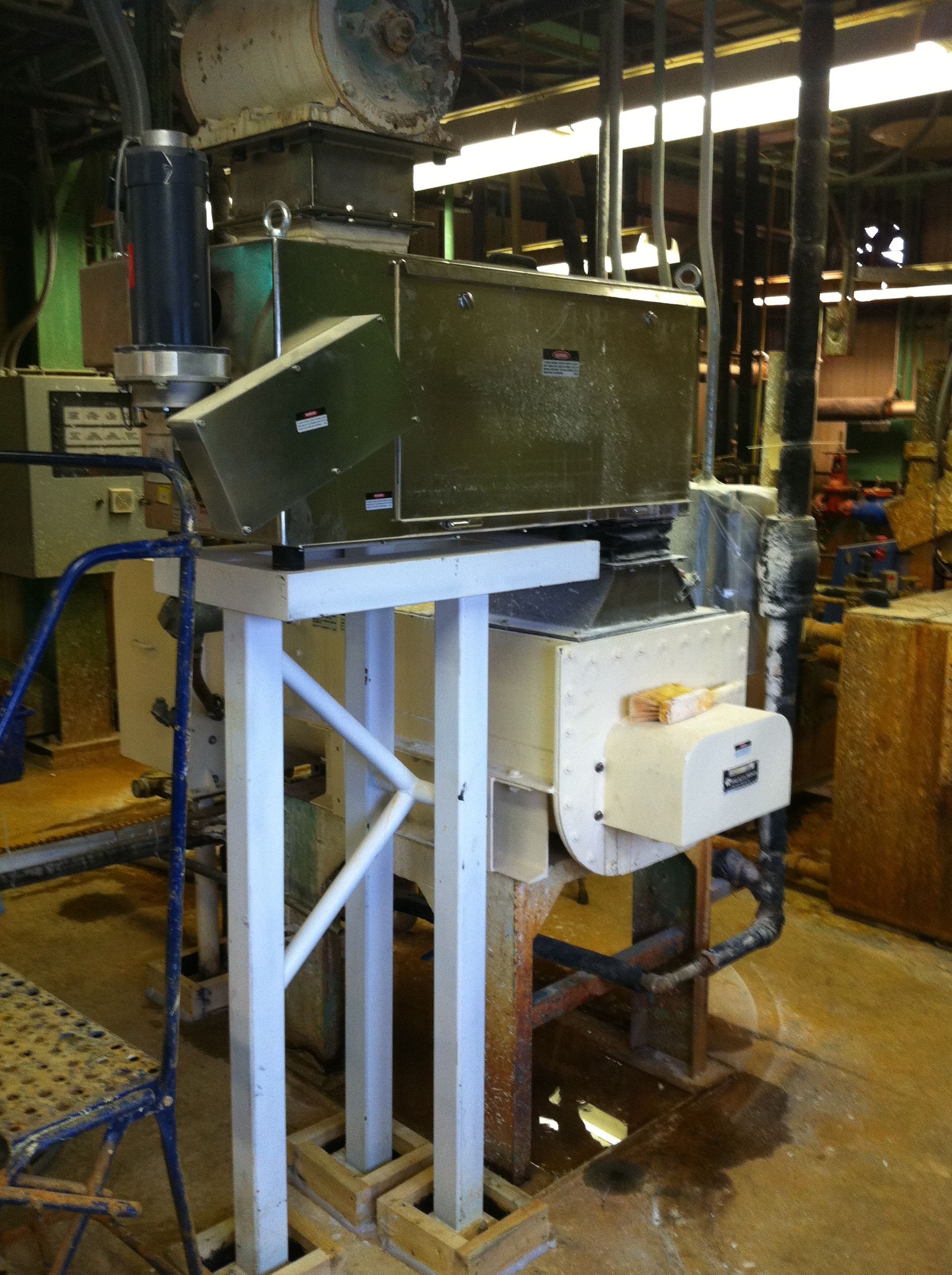
Sealed Tote Discharging for Dust and Moisture Control
P2O5 Batch Feeding System
Matrix Engineering has been involved with many operator safety improvement projects over the years.
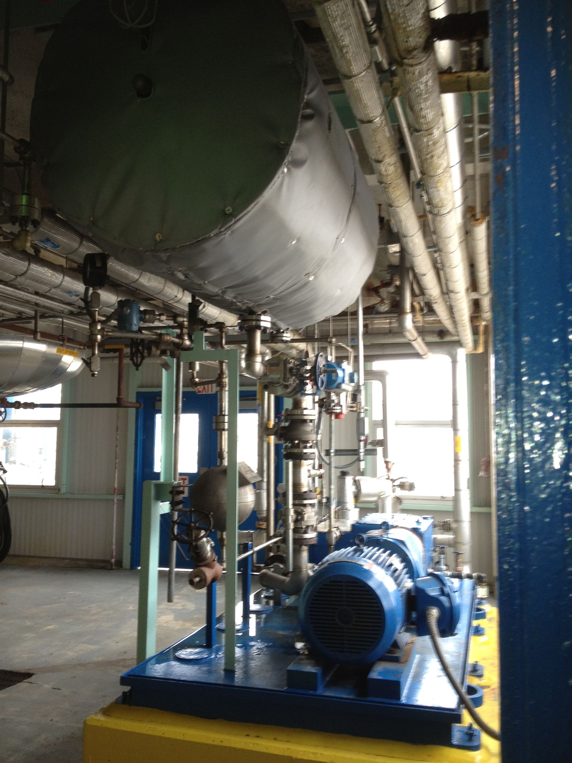
Matrix Engineering performed the mechanical and electrical design for the relocation for an existing steam spray dryer head tank. Space was so limited, we had to mount it tank on the ceiling...
Matrix Engineering provided the electrical and mechanical design for (2) new hydrated lime feed control systems for USEC’s water softening facility.
Matrix provided the civil, mechanical and electrical engineering for a capralactum tank and piping network with a new tempered water system for warming of the material for less viscous flow without risk of polymerizing the capralactum. This fluid is too stiff to move unless it is warmed. However, there is a risk of getting the material too hot in which case it reacts and hardens to a solid of hydrocarbon-chains which cannot be undone. The tempered water system consisted of exterior coils on the large storage tank as well a tracing along the insulated piping. Due to the critical nature of the fluid the tempered water was controlled to a very narrow allowable temperature range.
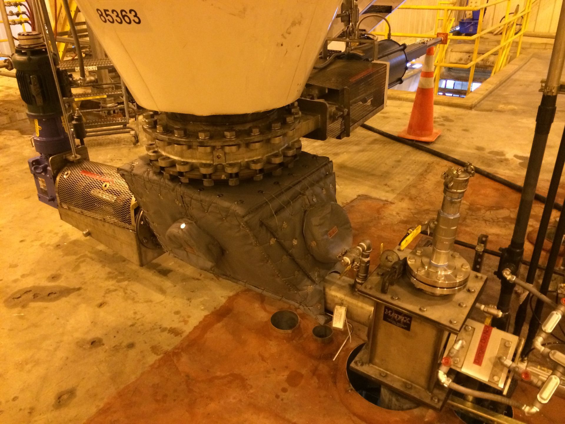
Based on the success of the pilot plant design, Matrix Engineering provided the structural, mechanical and electrical engineering necessary for installing continuous reactors in phases while removing existing batch reactors. The resulting reacted slurry is a thick, corrosive, sticky substance in which build-up on the reactor side walls was a major obstacle to engineer around. Our team worked very closely with RP on developing an acid feed system into the reactor that would accomplish continuous washing of the reactor side walls. Great care was also taken in the layout of the reactors so the reacted sticky slurry would fall through a large diameter (cleanable) chute directly into the dryer below. Included in this project was a dense phase pneumatic transporter for conveying alumina to receiving hoppers above the new reactors. The continuous reactors were installed and batch reactors removed so not to interfere with production of a sold-out product. Continuous reactor redundancy was installed in the initial phase to gain experience and determine reliability of the new process before fully committing to the new process. As confidence was gained in the new process the existing batch reactors were replaced with the new continuous design. This was an engineering challenge due to spatial constraints and design flexibility to utilize batch and continuous systems simultaneously. Eventually all of the batch reactors were replaced and they now operate solely on the continuous reaction process. Matrix Engineering has continued to improve on the original reactor design to the current 3rd generation continuous reactor.